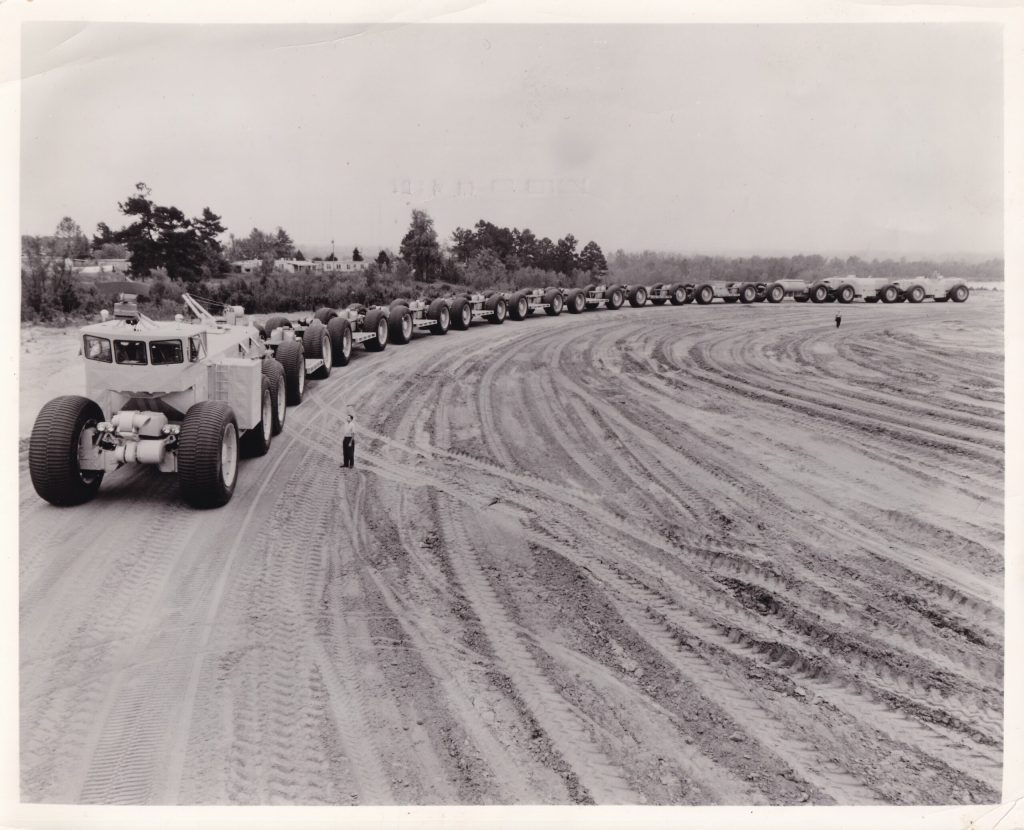
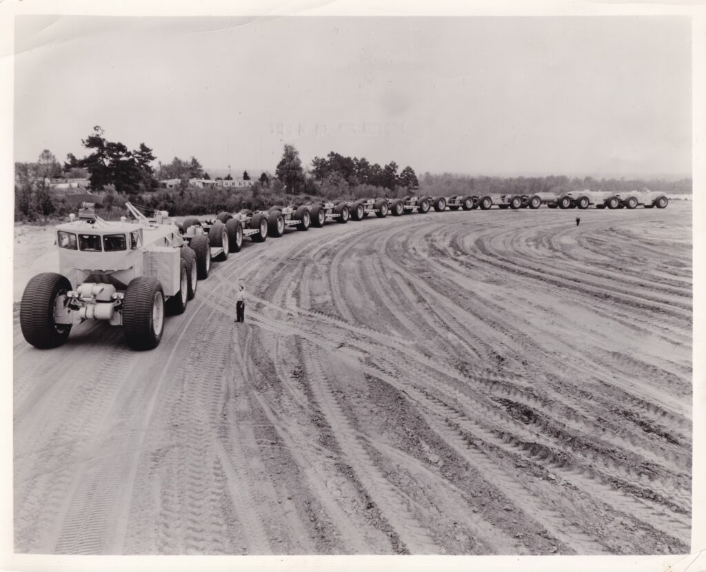
More specifically, the TC-497 appears to be at the previously known Red Hill. The photograph is dated February 23, 1962. This date is fairly close to accurate. In early March 1962, the TC-497 was shipped to the Army’s Yuma Proving Ground for additional testing.
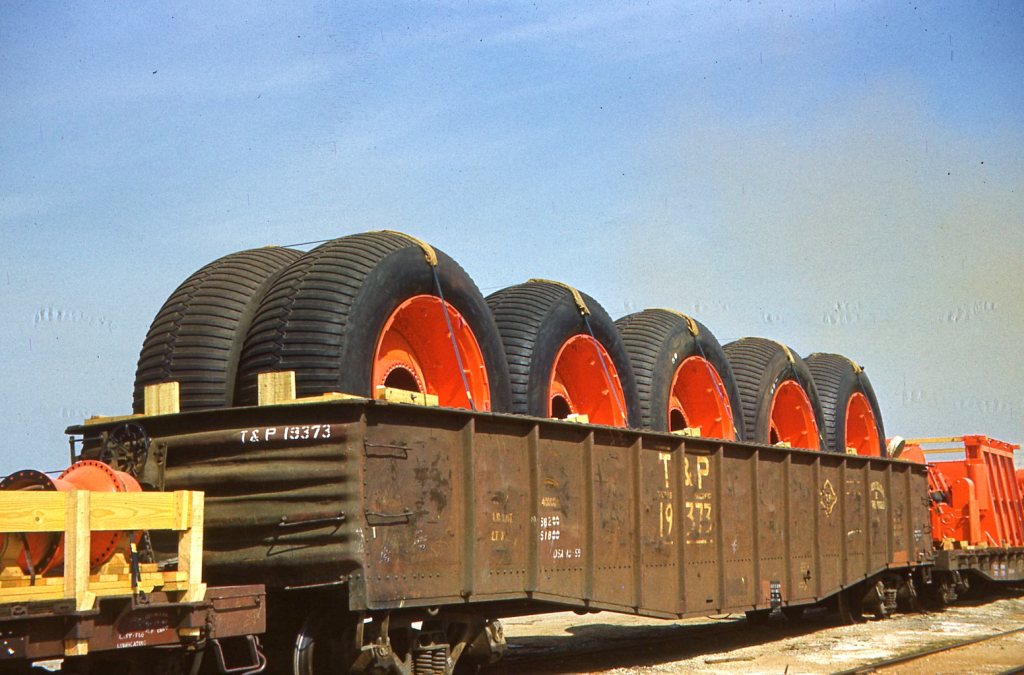
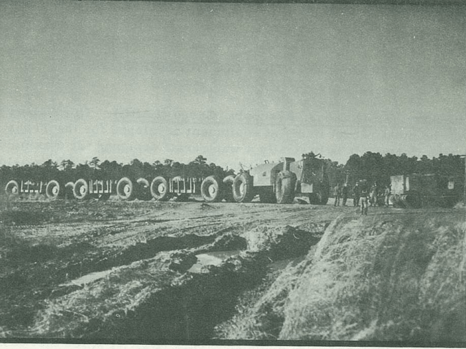
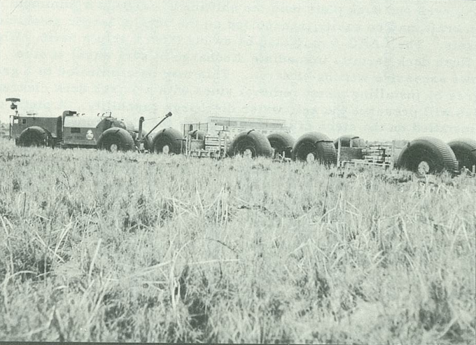
In March 1962, the TC-497 left LeTourneau’s Longview, TX factory for the Army’s Yuma Proving Ground (YPG). The Army had preliminarily accepted the TC-497. However, it needed several more years of testing and modifications. In the image below, you can see 10 of the 58 tires that were sent along to YPG. If you look to the bottom-left corner of the image, you can see LeTourneau’s Electric Drive, which includes the electric motor and driver (gear cluster).
Even the tires are packed. Image: Lloyd and Larry SmithTC-497 at Longview, TX. Image: Lloyd and Larry Smith
I have been communicating with the private seller of a new TC-497 8mm film. Even after the sale was complete, he continues to communicate the origins of the digitized film below. Through some careful and detail oriented observations, he rewrote my narrative on the film origin. This type of “people helping people” is one of the great rewards of writing the Overland Trains book. Thank you Paul.
“I bought this previously unreleased 8mm film from a private seller in England. The film’s seller bought it with a collection of other films and has since determined that the film was shot by an officer of the British Army’s Royal Engineers (most likely based at the Longmoor Military Railway in England). The officer was on secondment to Fort Eustis, VA from late 1962. It is likely that this secondment provided him with the opportunity to visit the Yuma Proving Ground.”
Video Timeline
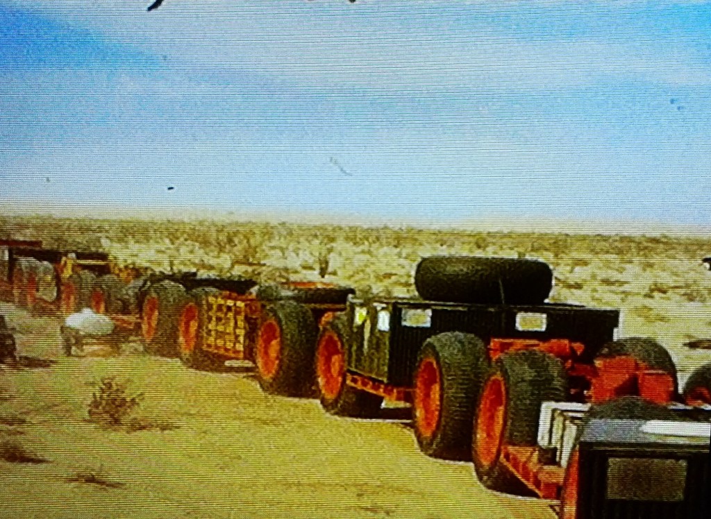
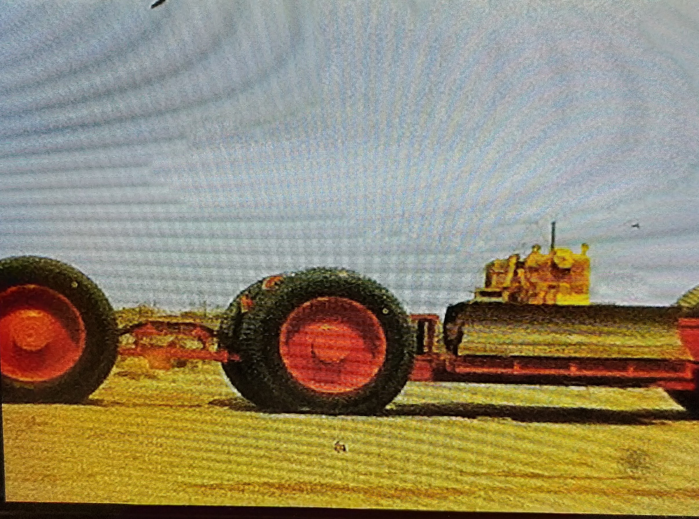
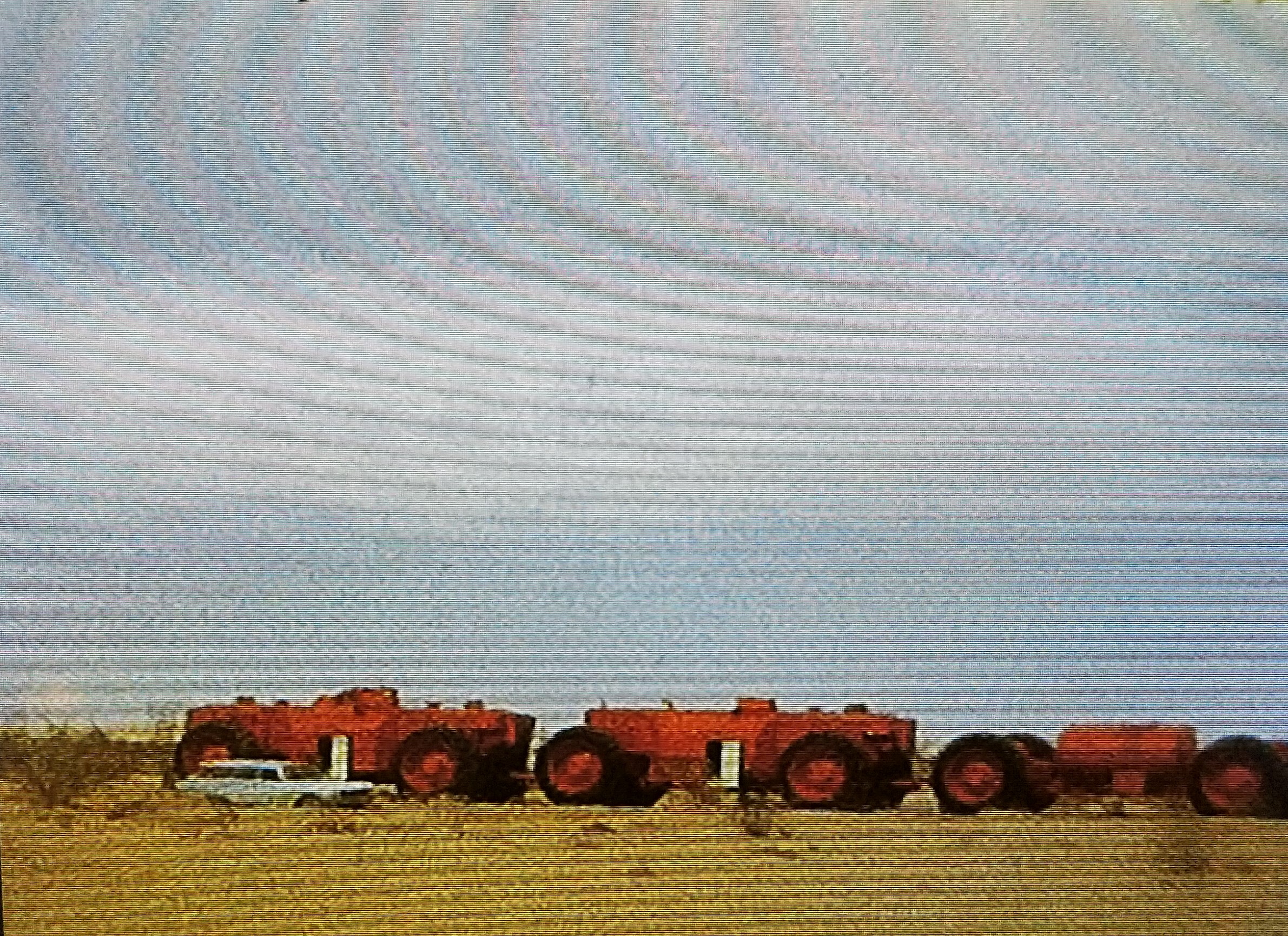
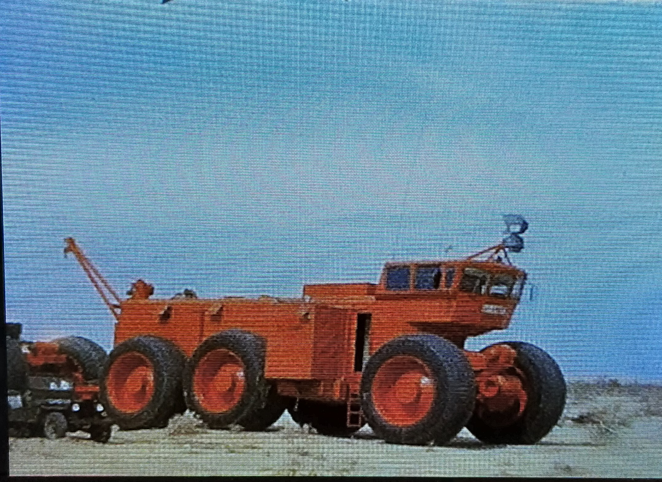
0-0:52 flying in an airplane 0:52-1:48 seeing the local sites 1:49-3:57 first site of TC-497 and support vehicles, helicopter ride 3:58-4:14 Yuma Proving Ground 4:15-5:23 TC-497 close-up walk around 5:24-6:17 tractor loaded on trailer, more close-ups and personnel walking around 6:18-6:28 inside control car with operator 6:29-7:20 external view of electrical cabling, more control car inside, 7:21-conclusion external view with man sitting on top of control car while driving, external view from power cars (rear)
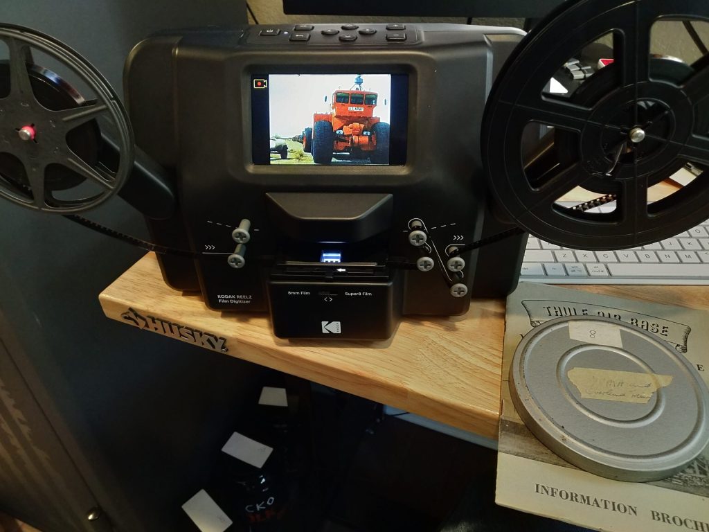
I acquired an 8mm film of the TC-497 in the Army’s Proving Ground, Yuma, AZ. The process is extremely slow going, as the digitizing projector captures every.single.frame. Soooo slow. Once it is digitized and formatted as an MP4, I will upload it to Vimeo for everyone to see. Until then, here are a few stills from the process.
Project Mobility occurred from June 5-10, 1961 at Fort Eustis, Virginia. During the 6 day exercise, The United States Army Transportation Training Command conducted daily demonstrations at Fort Eustis and Fort Story – Fort Story is a sub-installation of Fort Eustis. The exercise goals were to help the audience understand (1) the new techniques under development in resupply and amphibious areas and (2) demonstrate equipment recently added to the Army capabilities.
A paper booklet lists out the exercise scope, events schedule, observer participation, other equipment not shown during the exercise, maps of Fort Eustis and Fort Story, and administrative information.
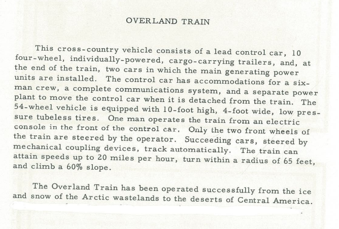
Some of the equipment not shown during the exercise, but highlighted in the booklet include the LARC, BARC, Rolling Liquid Transporter, GOER vehicle, Sikorsky S-60 helicopter, Landing Craft Retriever, and the Overland Train. Page 22 and 23 of the booklet show a brief description of the Overland Train. This description was for the TC-497.
Overland Train description from Project Mobility 1961, U.S. Army Fair Use.
However, the images below the TC-497 description were of the Sno-Train.
Sno-Train image from Project Mobility 1961, U.S. Army Fair Use.Sno-Train image from Project Mobility 1961, U.S. Army Fair Use.
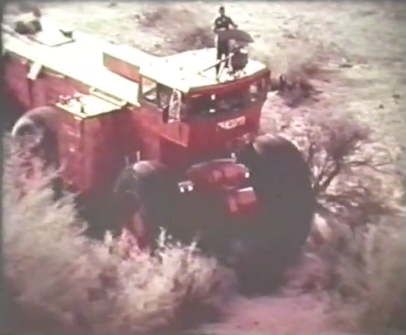
I was editing the TC-497 chapter early this morning and took a little detour in my video folder. Around three minutes into the video showing the TC-497 just after unloading at Yuma in 1962, I captured this still frame of an Army service member. He is standing on top of the TC-497, over 16 feet in the air while moving, and holding on to the radar unit. Let’s hope that was not activated during travel!
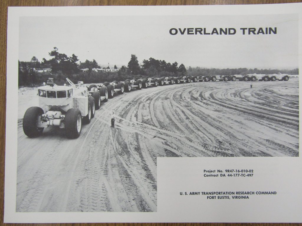
The Overland Train was the final train vehicle made by R. G. Letourneau. The back of this product card showed the technical specifications including an overall length of 572 feet and wide of 16 feet, 6 inches.
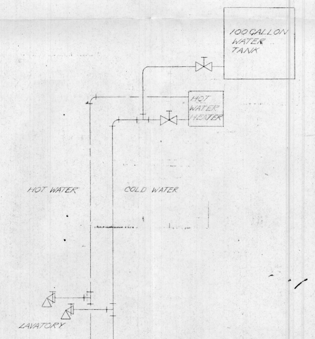
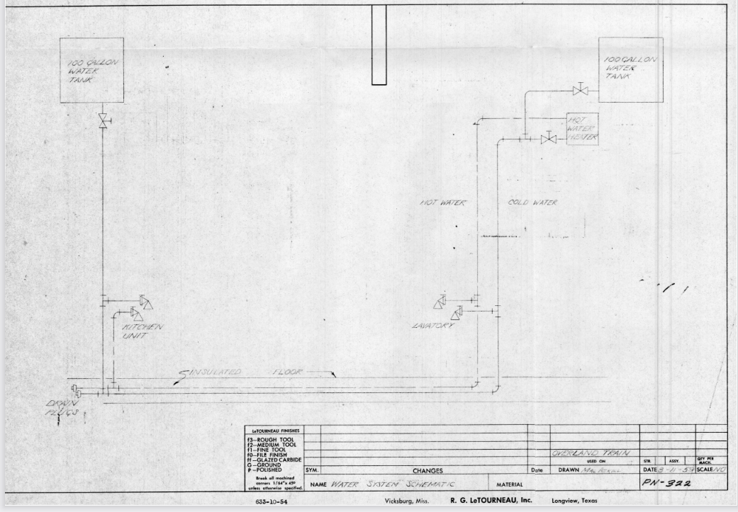
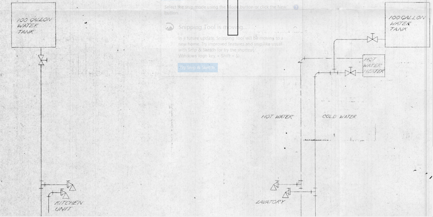
The Overland Mark 2 (Mark 2) was designed to support a crew of six and operate unsupported for a short period of time. The Mark 2 had a cold and hot water system that supplied water to the kitchen and a lavatory for washing hands and meal preparation. However, the water was not used for flushing the toilet. I’ll talk more in-depth about that in my book.
The Mark 2 contained 2*100 gallon water tanks. These tanks provided water under gravity to the hot water heater and the rest of the system. Water lines traveled underneath the insulated flooring. The drawing below shows that only one tank fed the hot water heater. Depending on the line pressure, it may be possible that the second 100-gallon tank could have also provided supply too. There is no mention or diagram of a wastewater system. It is entirely likely that the greywater from lavatory hand washing and the kitchen sink was drained outside as it was used.
The Mark 2 water system zoomed and rightThe Mark 2 water systemThe Mark 2 water system diagram close
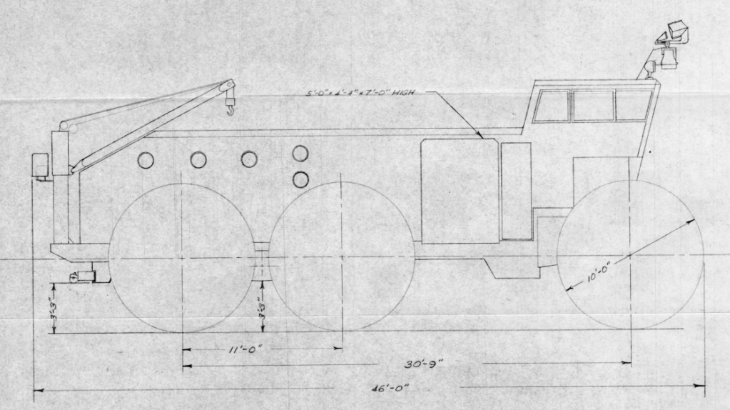
R. G. LeTourneau, Inc. and the Army had milestones built into The Overland Train Mark 2 (Mark 2) contract. These were defined as Phase I, Phase II, Phase III, and Phase IV. The Army and LeTourneau were designing and building some of the Mark 2 as they went along, including the suspension and interior layout. The following drawing is listed as Part Number, or PN-328. It is one of many drawings included in a Phase I design book created by R. G. LeTourneau, Inc. The drawing shows front-facing, passenger side, and top dimensions view, minus the removable side compartments. If you want to download the file, click the downward-facing arrow with the line under it on the top-right of the document area below or scroll to the bottom of this article.
The Mark 2 body, minus the tires, was 40 feet long. Once the tires are included in the measurements, the Mark 2 is 46 feet long as measured from the rear jib crane to the front tire.
It measured 16 feet, 6 inches wide, as measured from the outside edge of each tire. Each of the Firestone 120x48x68 tires was 4 feet wide!
If you measure the Mark 2 from the bottom of the tire to the top of the cab, it is 16 feet, 9 inches. Add the radar unit and the height extends to 20 feet, 7.5 inches tall.
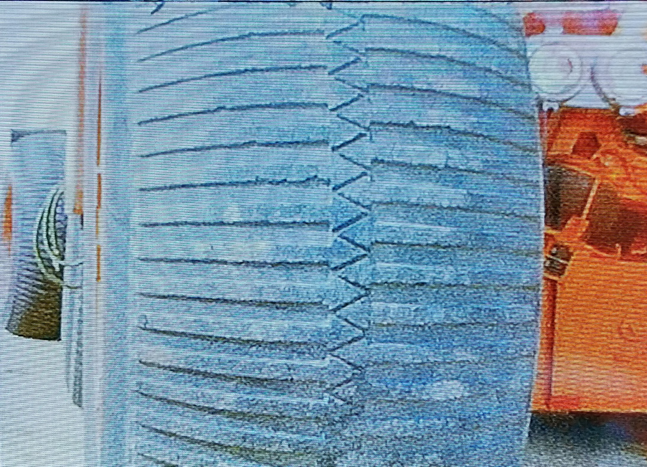
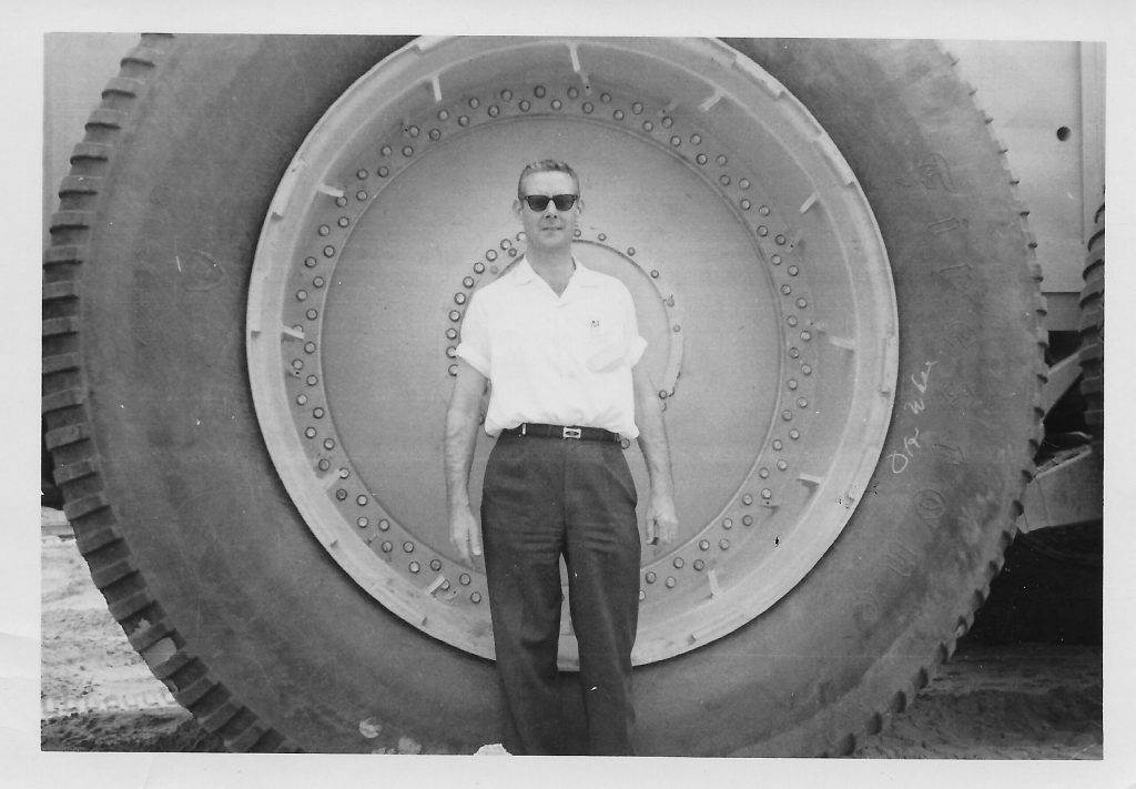
The Sno-Train and the Overland Mark 2 tires garnered a great deal of attention. Why shouldn’t they? the Firestone 120x48x68 tires are 4 feet wide and 10 feet tall. They were inflated to 20psi at the factory, but more commonly at around 7 to 10psi depending on terrain conditions. In this image, you can just make out the walking beam connecting the two tires together on the Mark 2.
Standing in front of the Overland Mark 2 tire. Image: Vic Vessakosol.