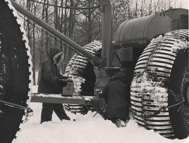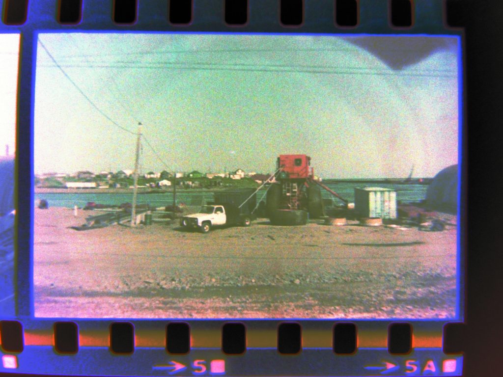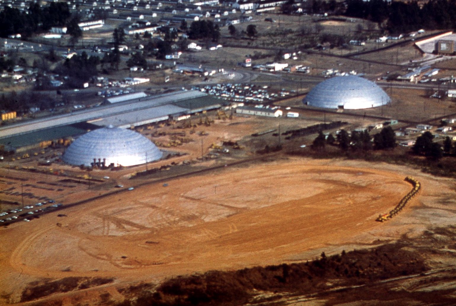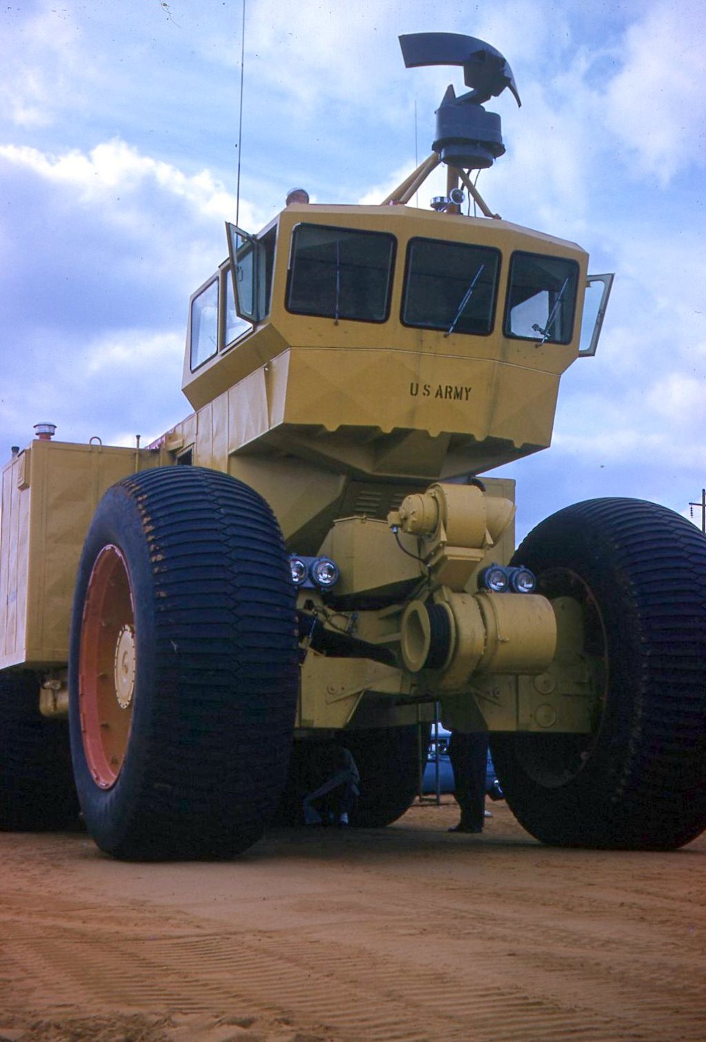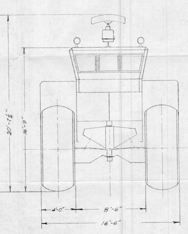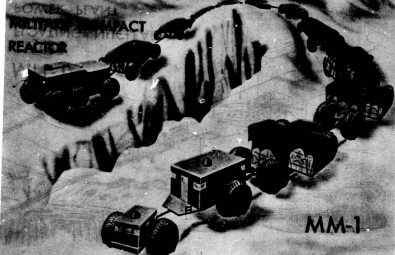
In 1960, the Army’s Nuclear Power Program had completed several nuclear reactors for research and testing purposes. Their micro-reactor (MCR (MM-1)) expected outputs were 500-800kW (MCR) and 2,000-3,000kW (MM-1). The MM-1 was targeted for use on a large logistical train and designed to help offset Petroleum, Oil, and Lubricants (POL) logistics needs in active war-time environments. During the 1960-1970 Army estimates, a theater of military operations would require fuel equivalent to 3.4 gallons/man/day to 7.5 gallons/man/day.

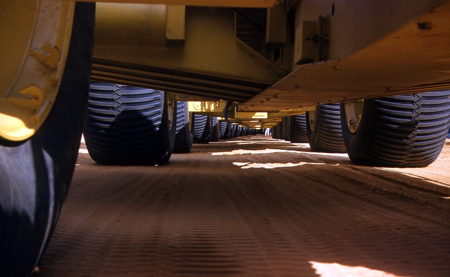
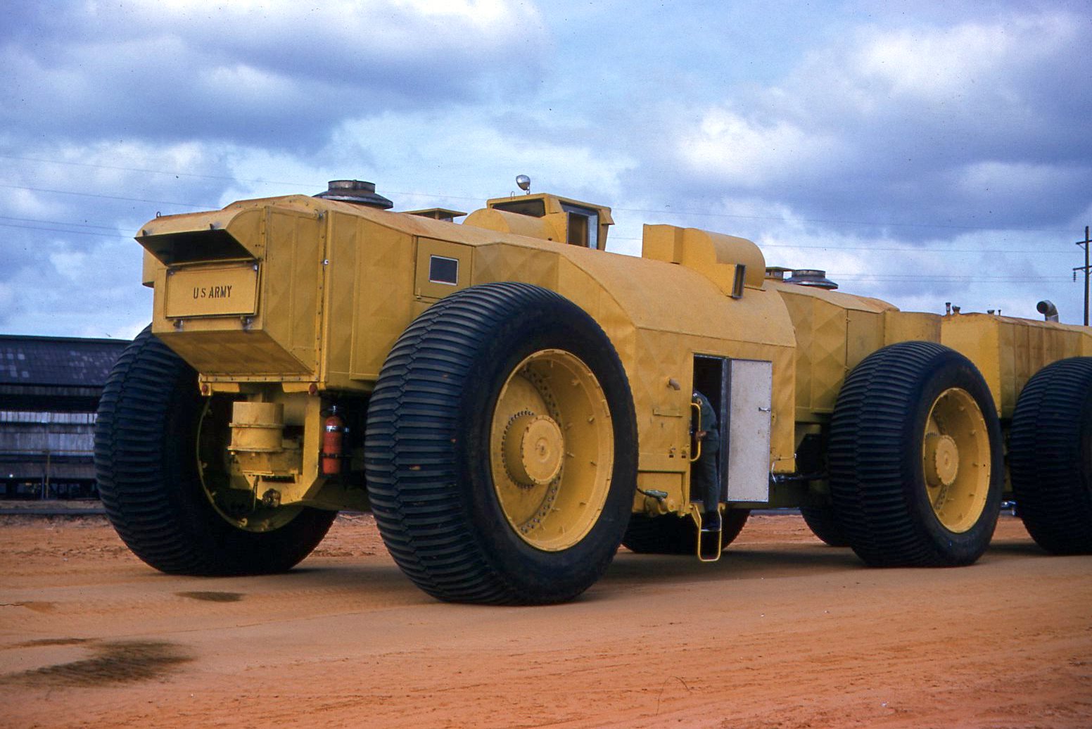
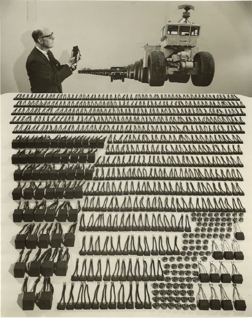
The MM-1 concept never came to reality, as the radiation shielding needed to protect men and equipment was too heavy. In 2016, the Defense Science Board (DSB) identified energy use as a major requirement for military operations. We have know this since before the Army Nuclear Power Program in the 1960’s. I am not sure why this point needed to be justified again.
Renewable power sources simply can not keep up with the military demands, which catalyzed the military to restart their efforts at a meltdown-proof (see TRISO fuel), miniature nuclear reactor concepts as Project Pele. As of March 22, 2021, to companies, BWXT Advanced Technologies and X-energy were given the go-ahead for their final mobile micro-reactor designs.
Similar to the 1960’s designs, these modern day micro-reactors are targeted at electrical output between 1mW to 5mW (1,000-5,000kW). I doubt we will see another logistical cargo train concept anytime soon. If you want to read more about Project Pele and micro-reactors, here are a few good places to start.